

How to Identify and Solve the Problem That Piezoelectric Products Unable to Achi
Hello everyone, today professional CoreMorrow engineer will introduce the identification and solutions for piezoelectric products that cannot be used in closed loop due to zero offset.
The first step: The identification method of the piezoelectric product unable to close the loop due to the zero offset
We take CoreMorrow E01.D6 piezoelectric controller and CoreMorrow VS12 series piezoelectric ceramic actuators as examples to introduce. The adjustment methods of other products are similar.
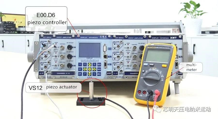
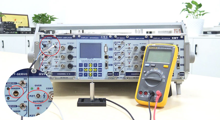
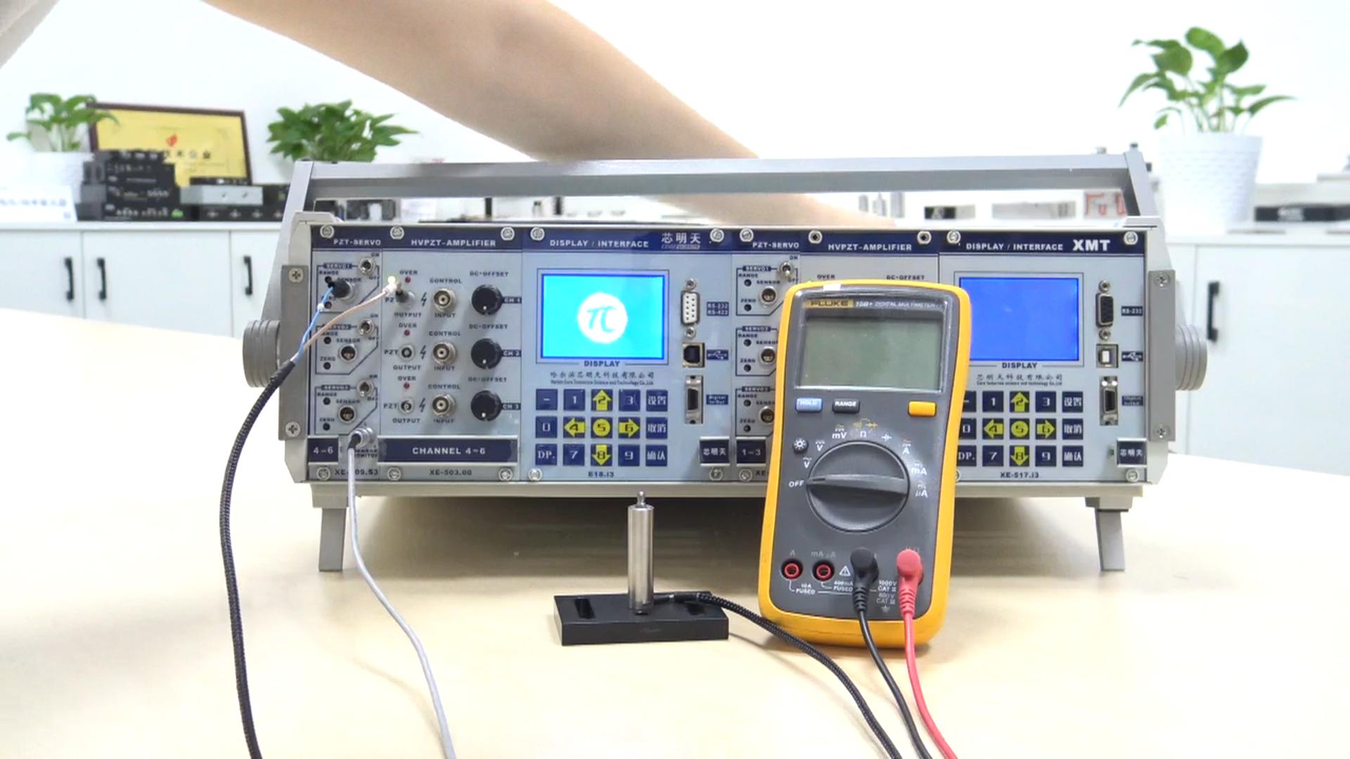
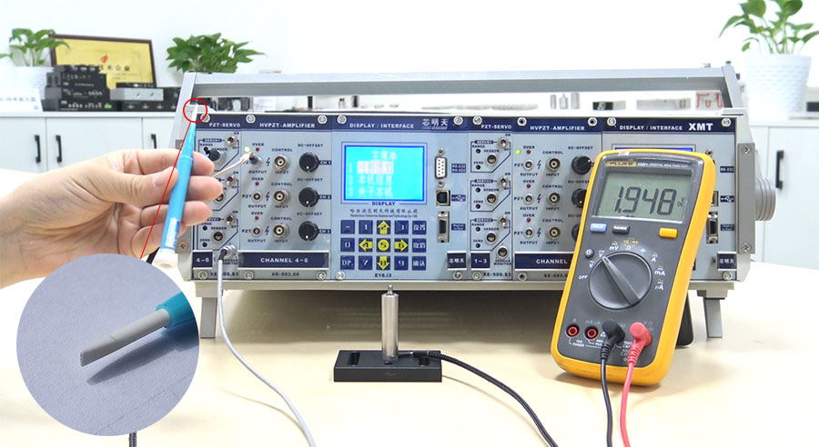
Firstly, correctly connect the drive and sensing lines of the piezoelectric ceramic actuator to the corresponding PZT and SENSOR interfaces on the E01.D6 piezoelectric controller panel.
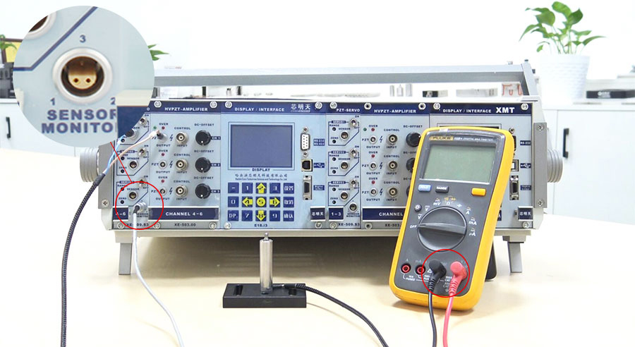
Secondly, connect the sensor monitor SENSOR MONITOR output port on the piezoelectric controller with the multimeter through the sensor monitor output line.
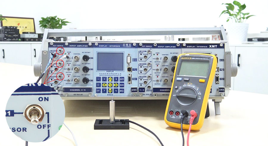
Thirdly, adjust the open/closed loop Servo state of all output channels of the piezoelectric controller to the open loop state (that is, turn it OFF).
After the above operations are performed, turn on the piezoelectric controller (the power switch of E01.D6 is on the rear panel).
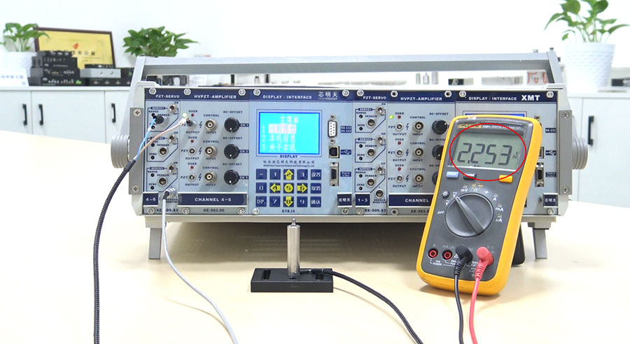
Adjust the multimeter to the DC voltage range.
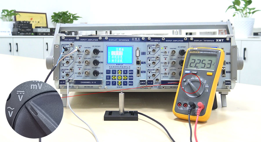
Under normal conditions, the voltage displayed on the multimeter is in the range of 0~0.4V, and at this time, it can be seen that the voltage value displayed by the multimeter has far exceeded the normal output voltage range. This shows that the zero point has been greatly biased, causing the piezoelectric products to be unable to operate in a closed loop.
The second step: The solution to the piezoelectric product unable to close the loop caused by the zero offset
Now Let’s talk about how to solve this problem.
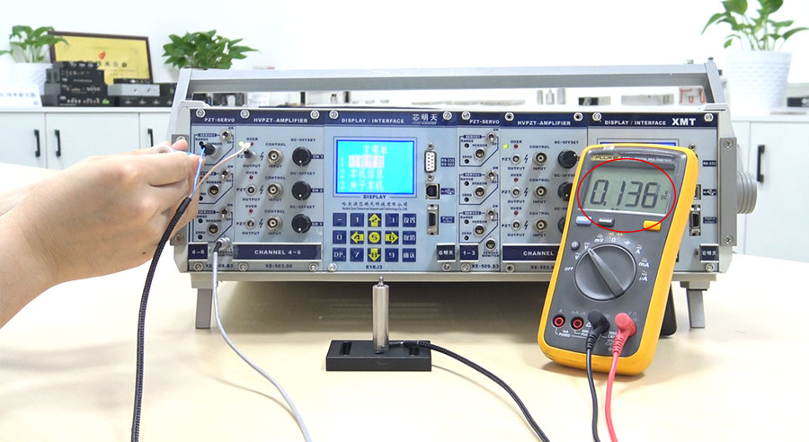
Firstly, find the position of the ZERO potentiometer on the panel of the piezoelectric controller.
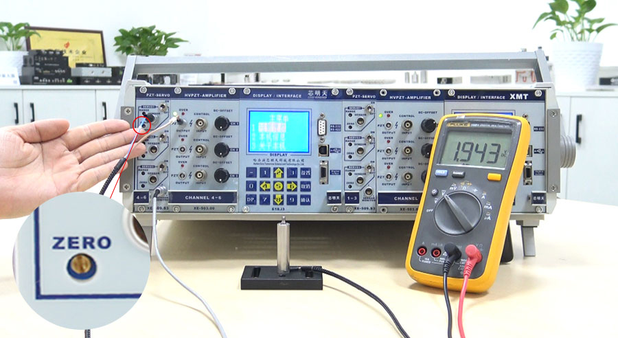
Then prepare a flat-blade screwdriver, and adjust the ZERO potentiometer with a flat-blade screwdriver.
At the same time, pay attention to the voltage value change on the multimeter. The counterclockwise adjustment will make the monitor output voltage smaller, and the clockwise adjustment will make the monitor output voltage larger. Adjust to the output voltage value on the multimeter within the range of 0~0.4V to stop.
Then, set the piezoelectric controller to output the maximum voltage value. After the setting is complete, set the output voltage to 0V, and observe the voltage value change on the multimeter at this time.

If it is not within the range of 0~0.4V, you still need to adjust the potentiometer and adjust the voltage displayed on the multimeter to within the range of 0~0.4V.
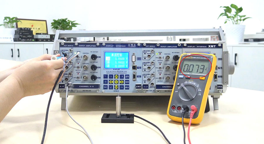
After adjustment, repeat the above operations: set the maximum output voltage and set the output voltage of 0V until the voltage displayed on the multimeter is within the range of 0~0.4V after the operation, then the adjustment operation is completed.
The third step: Verification of validity after zero offset adjustment operation
After making the above adjustments, let's verify whether the adjustments are effective.
Adjust the open/closed loop Servo state of the corresponding output channel to the closed loop state (that is, turn it ON).
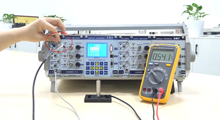
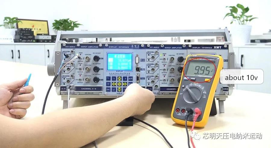
Set the maximum displacement value of the output piezoelectric ceramic actuator. At this time, we can observe that the voltage range displayed on the multimeter is about 10V;
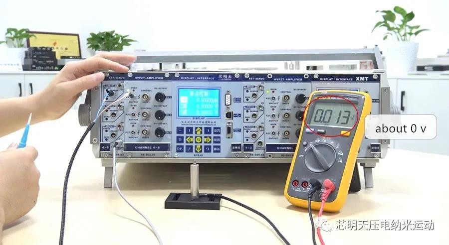
Then set the output zero displacement and observe the voltage displayed on the multimeter. If it is around 0V, it proves that the zero offset problem has been solved, and the piezoelectric product can be used in a normal closed loop.
- Previous article:Hollow Three-Dimensional Piezo Deflection Mirror in Interference Scanning
- Next article:12-Channel Piezo Servo Controller
Sweep, get the latest information on core tomorrow
Address:1F, Building I2, No.191 Xuefu Road, Nangang District, Harbin, China
Tel:0451-86268790
Piezo · Nano · Motion
