
- Introduction
- Feedback
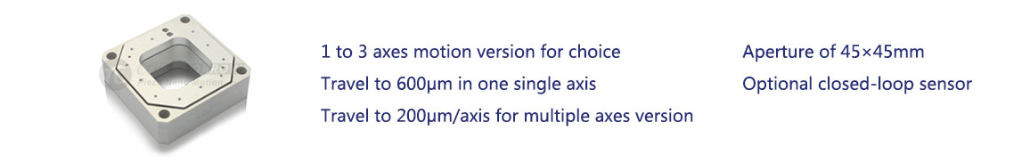
Characteristics

|
|
|
|
|
|
|
|
|
|

Applications
|
|
|
|
|
|
|
|
Note: Above are measured using E00/E01 piezo controllers. The max driving voltage can be -20V~150V; Recommended voltage 0~120V for high-reliability and long-term use.
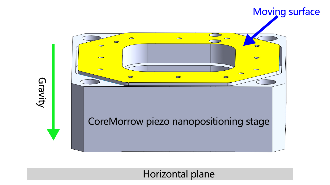
| Mounting Method |
Horizontal Mounting |
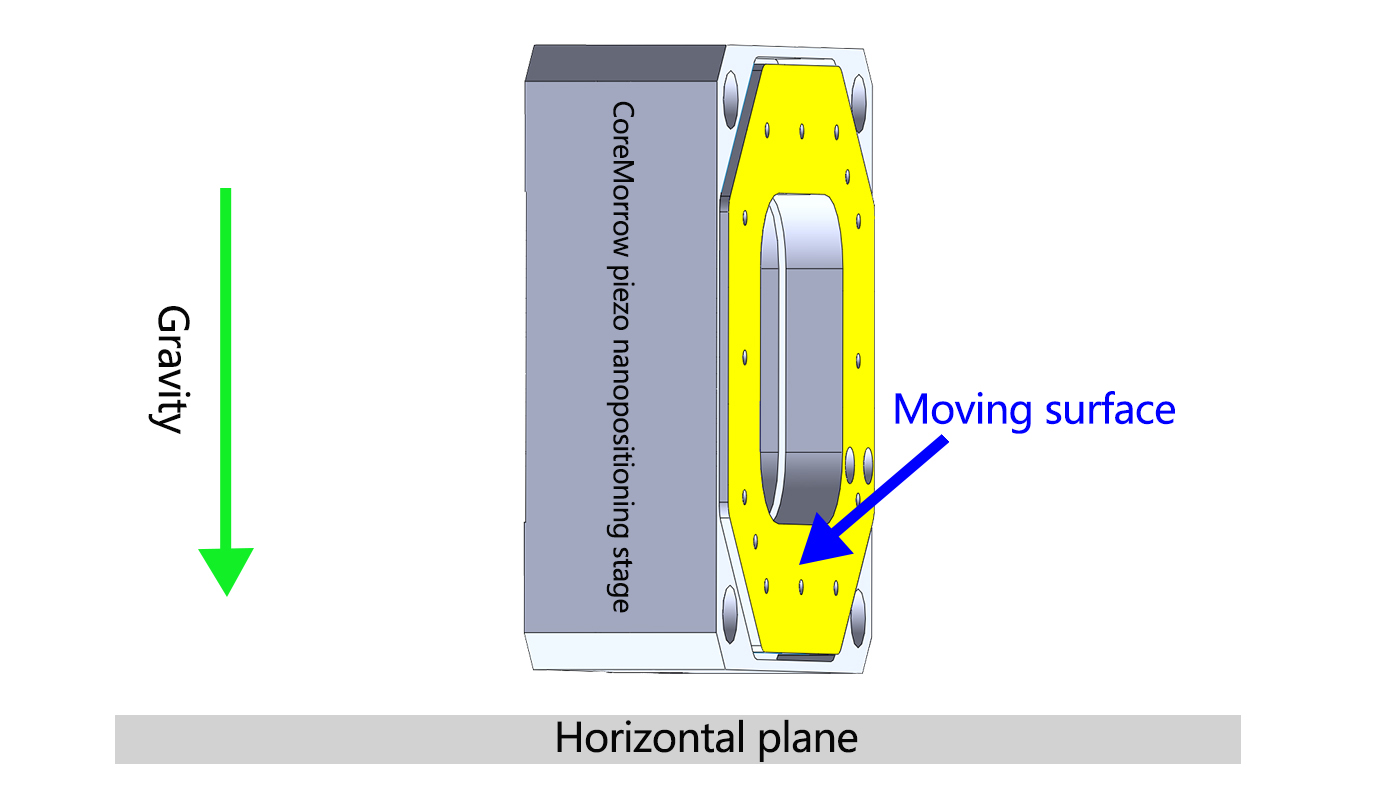
Vertical Mounting |
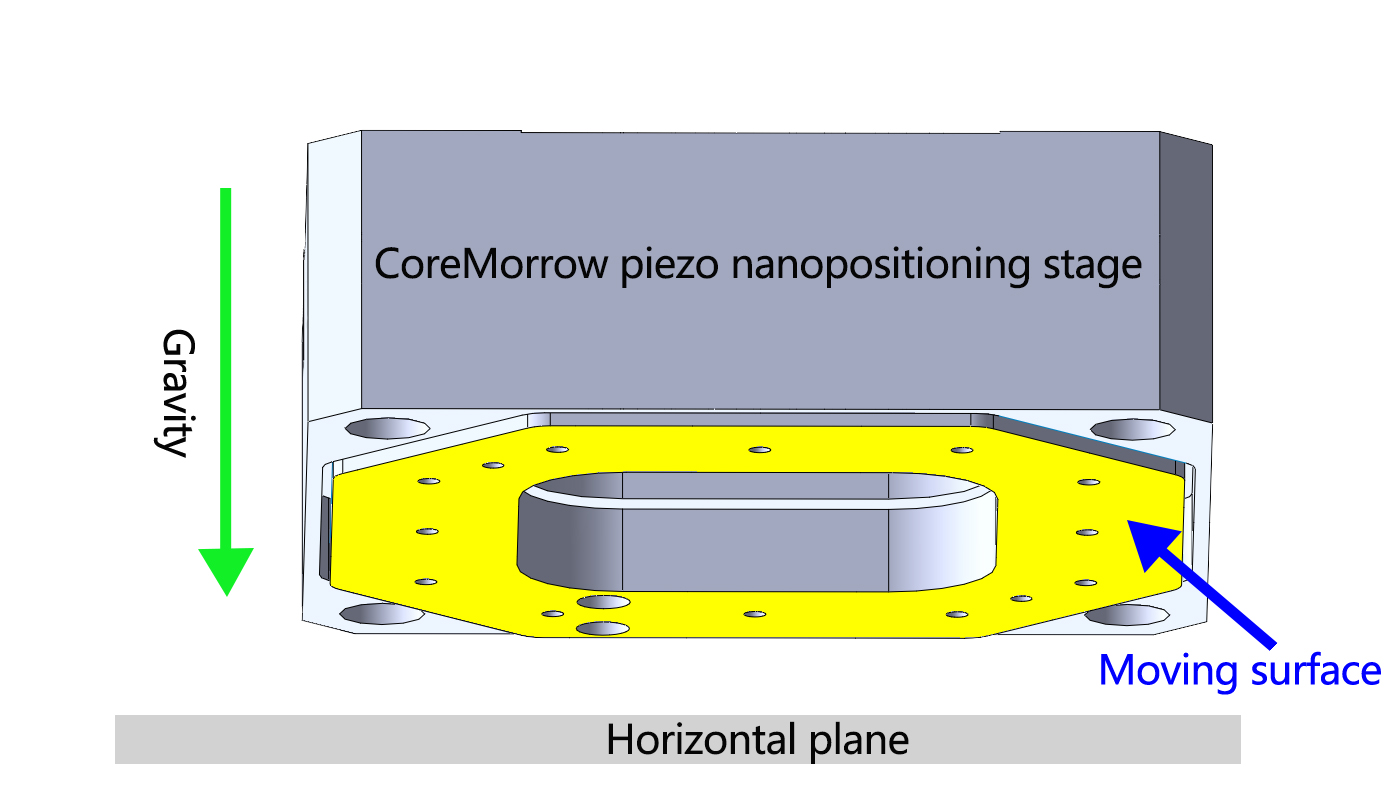
Inverted Mounting |
| Definition |
Place the PZT platform horizontally for installation, with the moving surface located above the PZT platform and parallel to the horizontal plane.
PS: Default direction for carrying capacity in the parameter table
|
Place and install the PZT platform vertically, with the moving surface parallel to the direction of gravity
|
Place the PZT platform horizontally, but the moving surface is located below the PZT platform |
| Diagram |
 |
 |
 |
| Note |
When the mounting method is selected as vertical mounting, pay attention to the outlet port |
||


Sweep, get the latest information on core tomorrow
Address:1F, Building I2, No.191 Xuefu Road, Nangang District, Harbin, China
Tel:0451-86268790
Piezo · Nano · Motion
