
- Introduction
- Technical Data
- Dimensions
- Feedback
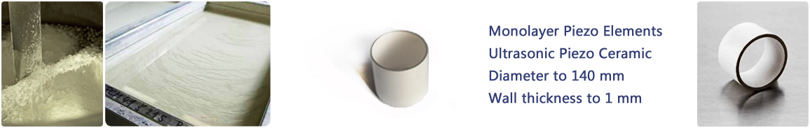
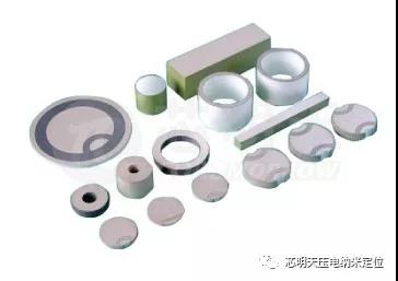
Harbin Core Tomorrow(CoreMorrow for short) provides piezoelectric components, which could be widely selected in terms of shape and size to suit your application.
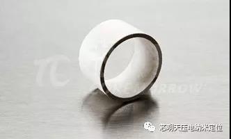
CoreMorrow piezoelectric ceramics (also often called ultrasonic ceramics) contains only one piezoelectric ceramic layer inside, and there is no electrode layer inside, only the electrode layer on the outer surface, unlike the multilayer piezoelectric ceramics, there are many ceramic layers and electrode layers. It could be used for cutting without destroying the single-layer ceramic corresponding to the positive and negative electrodes.
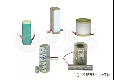
| Comparison of piezo component and multilayer piezo stack | ||
|
Attributes |
Piezo component |
Multilayer piezo stack |
|
Appearance |
|
|
|
Driving voltage |
High(~1kV/mm) |
Low(60V/150V/200V) |
|
Displacement |
small, nanometer-scale |
large, micrometer-scale |
|
Resonant frequency |
100kHz~6.6MHz |
50Hz~100kHz |
|
Capacitance |
nF-scale |
nF~μF-scale |
| Appearance and Size | |
|
Appearance |
Size |
|
|
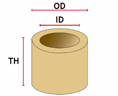
Tube |
CoreMorrow Piezo Component Electrode

Standard electrode is silver. Standard electrode patterns is Solid, the cylinder inner and outer electrode, inner is positive and outer is negative. Customization patterns are as followings:

Piezo Component Withstand Voltage
Material
PZT5
PZT8
AC
200~280V/mm
360~440V/mm
DC
400~560V/mm
720~880V/mm
Max Driving Voltage
PZT4
360~440V/mm
720~880V/mm
Resonant Frequency
| Plate resonant frequency | |
|
Thickness[mm] |
Resonant frequency[kHz] |
|
20 |
100 |
|
10 |
200 |
|
4 |
500 |
|
2 |
1000 |
|
1.4 |
1500 |
|
1 |
2000 |
|
0.5 |
4000 |
|
0.45 |
4700 |
|
0.3 |
6600 |
After the piezoelectric ceramics are installed in the equipment, the resonant frequency will be reduced, and the specific parameters need to be structured.
Displacement CALA.
Using the inverse piezoelectric effect, that is, applying a voltage to the piezoelectric ceramic, the piezoelectric ceramic will be deformed and displaced under the influence of the electric field.
1、Displacement cala.
Displacement of piezoelectric ceramic under the withstand voltage is about 1‰ of the length of displacement direction. For example, 1mm thick ceramic sheet has a withstand voltage of 1000V, and at 1000V, its displacement is about 1μm.
2、Plate piezo ceramic displacement cala.
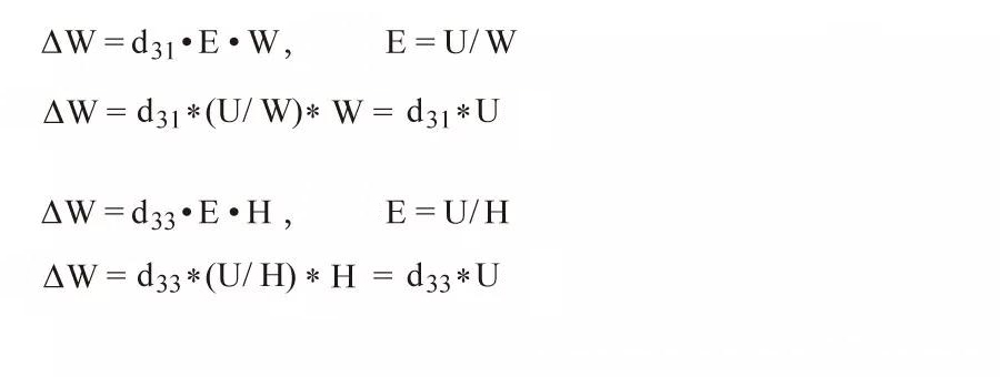
U:voltage[V] , H:height of piezo ceramic[m] , E:electric field intensity[V/m] , d:piezoelectric coefficients[m/V] , W:width of piezo ceramic[m]
It can be seen from the above formula that the displacement of piezo ceramics is only related to the material and the driving voltage, and for the same material and different heights of piezo ceramic, as long as the same voltage is applied (Note: the voltage cannot exceed the voltage that it can withstand ), the resulting displacement is basically the same.
The displacement of other shapes can also be estimated according to this calculation formula.
Static Voltage CALA.
When the piezoe ceramic is used as a sensor, its positive piezoelectric effect is used, that is, it is deformed by applying an external force to output electric charge.
Disc static voltage cala.:

g33:material constant,
F:froce,
OD:outer diameter,
ID:inner diameter
Recommend Piezo Controller
| Parameter | |||
|
Model |
Output voltage[V] |
Output power[W] |
Bandwidth(-3dB) |
|
E01/00 |
120V |
20W |
0~50KHZ |
|
50V |
20W |
0~100KHZ |
|
|
40V |
20W |
0~150KHZ |
|
|
E2031 |
300V |
18W |
0~500kHz |
|
E4011 |
160V |
80W |
0~1MHz |
|
E2021 |
170V |
42.5W |
0~1.5MHz |
|
E1200 |
35V |
17.5W |
0~24MHz |
Roughness: Rz 5-10, Ra 0,7-1,3.
Flatness: +/-10µm, depends the size.
Acoustic impedance: radialoscillation.
Output power: the output power is related to the frequency of ceramic vibration and driving voltage, etc., max to 40-50W/cm3 on the resonant frequency point.
Material Technical Data:
|
Properties |
Symbol & unit |
NCE40 |
NCE41 |
NCE46* |
NCE51 |
NCE53 |
NCE55 |
NCE56 |
NCE57* |
NCE59* |
NCE80 |
NCE81 |
|
Dielectric Properties(Tolerance +/-10%) |
|
|
||||||||||
|
Relative Dielectric Constant |
εT33 / ε0 |
1250 |
1350 |
1300 |
1900 |
1600 |
5000 |
2900 |
1800 |
2900 |
1050 |
1020 |
|
Dielectric Loss Factor |
tgδ [10-4] |
25 |
40 |
30 |
150 |
130 |
220 |
140 |
170 |
190 |
20 |
17 |
|
Dielectric Loss Factor at 400V/mm |
tgδ [10-4] |
140 |
200 |
|
|
|
|
|
|
|
100 |
60 |
|
Electromechanical Properties(tolerance +/-5%) |
||||||||||||
|
Electromech. Coupling Factors** |
kp |
0.58 |
0.57 |
0.57 |
0.65 |
0.56 |
0.62 |
0.64 |
0.59 |
0.64 |
0.55 |
0.55 |
|
|
k31 |
0.34 |
0.33 |
0.33 |
0.38 |
0.32 |
0.39 |
0.37 |
0.33 |
0.37 |
0.30 |
0.30 |
|
|
k33 |
0.70 |
0.68 |
0.68 |
0.74 |
0.65 |
0.72 |
0.74 |
0.70 |
0.75 |
0.68 |
0.69 |
|
|
kt |
0.50 |
0.50 |
0.47 |
0.50 |
0.47 |
0.50 |
0.50 |
0.47 |
0.52 |
0.48 |
0.47 |
|
Piezoelectric Charge Constants |
-d31 [10-12 C/N] |
140 |
130 |
130 |
195 |
150 |
260 |
250 |
170 |
240 |
100 |
100 |
|
|
d33 [10-12 C/N] |
320 |
310 |
290 |
443 |
360 |
670 |
580 |
425 |
575 |
240 |
255 |
|
Piezoelectric Voltage Constants |
-g31[10-3 Vm/N] |
11 |
11 |
11 |
13 |
9 |
9 |
9 |
11 |
10 |
11 |
11 |
|
|
g33 [10-3Vm/N] |
27 |
25 |
28 |
26 |
23 |
19 |
20 |
27 |
23 |
27 |
28 |
|
Frequency Constants |
NEp [m/s] |
2160 |
2280 |
2230 |
1925 |
2180 |
1970 |
2000 |
2010 |
1970 |
2270 |
2320 |
|
|
NDt [m/s] |
1980 |
2000 |
2040 |
2000 |
2040 |
1990 |
2030 |
1950 |
1960 |
2050 |
2130 |
|
|
NE1 [m/s] |
1470 |
1600 |
1500 |
1370 |
|
|
1530 |
1400 |
1410 |
1610 |
1630 |
|
|
ND3 [m/s] |
1340 |
1500 |
1800 |
1320 |
|
|
1400 |
1500 |
1500 |
1500 |
1500 |
|
Physical Properties(tolerance +/-5%) |
||||||||||||
|
Mechanical Quality Fator |
Qm |
700 |
1400 |
>1000 |
80 |
80 |
70 |
80 |
80 |
90 |
1000 |
1400 |
|
Density |
ρ [103 kg/m3] |
7.75 |
7.90 |
7.70 |
7.85 |
7.60 |
8.00 |
7.65 |
7.70 |
7.45 |
7.80 |
7.73 |
|
Elastic Compliances |
sE11 [10-12m2/N] |
13 |
13 |
13 |
16 |
16 |
17 |
18 |
17 |
17 |
11 |
16 |
|
|
sE33 [10-12 m2/N] |
17 |
16 |
20 |
19 |
18 |
21 |
20 |
23 |
23 |
14 |
17 |
|
Curie Tempreture |
Tc[°C] |
318 |
284 |
330 |
360 |
340 |
159 |
242 |
350 |
235 |
307 |
307 |
|
*) For multilayer components only. |
||||||||||||
|
The values listed above are for reference purposes only and cannot be applied unconditionally to other shapes and dimensions. Values vary depending on the components' actual shape, surface finish, shaping process and post-processing. |
||||||||||||
| Overview of the range of possibilities | |||||||||||||||||
|
OD (mm) |
TH*(mm) |
WTH**(mm) |
|||||||||||||||
|
|
1 |
5 |
10 |
15 |
20 |
25 |
30 |
35 |
40 |
45 |
50 |
55 |
60 |
1 |
2 |
2.5 |
5 |
|
5 |
|
√ |
√ |
√ |
|
|
|
|
|
|
|
|
|
√ |
|
|
|
|
8 |
√ |
√ |
√ |
√ |
√ |
√ |
√ |
|
|
|
|
|
|
√ |
|
|
|
|
10 |
√ |
√ |
√ |
√ |
√ |
√ |
√ |
|
|
|
|
|
|
√ |
|
|
|
|
15 |
√ |
√ |
√ |
√ |
√ |
√ |
√ |
√ |
√ |
√ |
√ |
|
|
√ |
|
|
|
|
20 |
√ |
√ |
√ |
√ |
√ |
√ |
√ |
√ |
√ |
√ |
√ |
|
|
√ |
|
|
|
|
25 |
√ |
√ |
√ |
√ |
√ |
√ |
√ |
√ |
√ |
√ |
√ |
|
|
√ |
|
|
|
|
30 |
√ |
√ |
√ |
√ |
√ |
√ |
√ |
√ |
√ |
√ |
√ |
|
|
√ |
|
|
|
|
35 |
√ |
√ |
√ |
√ |
√ |
√ |
√ |
√ |
√ |
√ |
√ |
|
|
√ |
|
|
|
|
40 |
√ |
√ |
√ |
√ |
√ |
√ |
√ |
√ |
√ |
√ |
√ |
|
|
√ |
|
|
|
|
50 |
√ |
√ |
√ |
√ |
√ |
√ |
√ |
√ |
√ |
√ |
√ |
|
|
|
√ |
|
|
|
55 |
√ |
√ |
√ |
√ |
√ |
√ |
√ |
√ |
√ |
√ |
√ |
|
|
|
√ |
|
|
|
60 |
√ |
√ |
√ |
√ |
√ |
√ |
√ |
√ |
√ |
√ |
√ |
|
|
|
√ |
|
|
|
65 |
√ |
√ |
√ |
√ |
√ |
√ |
√ |
√ |
√ |
√ |
√ |
|
|
|
|
√ |
|
|
70 |
√ |
√ |
√ |
√ |
√ |
√ |
√ |
√ |
√ |
√ |
√ |
|
|
|
|
√ |
|
|
80 |
√ |
√ |
√ |
√ |
√ |
√ |
√ |
√ |
√ |
√ |
√ |
|
|
|
|
√ |
|
|
90 |
√ |
√ |
√ |
√ |
√ |
√ |
√ |
√ |
√ |
√ |
√ |
|
|
|
|
√ |
|
|
100 |
√ |
√ |
√ |
√ |
√ |
√ |
√ |
√ |
√ |
√ |
√ |
|
|
|
|
√ |
|
|
110 |
√ |
√ |
√ |
√ |
√ |
√ |
√ |
√ |
√ |
√ |
√ |
|
|
|
|
√ |
|
|
120 |
√ |
√ |
√ |
√ |
√ |
√ |
√ |
√ |
√ |
√ |
√ |
|
|
|
|
√ |
|
|
140 |
√ |
√ |
√ |
√ |
√ |
√ |
√ |
|
|
|
|
|
|
|
|
|
√ |
Sweep, get the latest information on core tomorrow
Address:1F, Building I2, No.191 Xuefu Road, Nangang District, Harbin, China
Tel:0451-86268790
Piezo · Nano · Motion
