

- Introduction
- Feedback
产品特点

|
|
|
|
|

| Technical Data | ||||
|
Type |
P92.X25S |
P92.X25K |
Units |
|
|
Active axes |
X |
X |
|
|
|
Travel range(0~120V) |
22 |
22 |
μm±10% |
|
|
Max.travel range(0~150V) |
28 |
28 |
μm±10% |
|
|
Drive control |
1 driving channel 1 sensing channel |
1 driving channel |
|
|
|
Integrated sensor |
SGS |
- |
|
|
|
Resolution |
1 |
0.5 |
nm |
|
|
Unloaded resonant frequency |
5000 |
5000 |
Hz±20% |
|
|
Unloaded step time |
0.3 |
0.3 |
ms |
|
|
Stiffness |
50 |
50 |
N/μm±20% |
|
|
Blocking force |
1000 |
1000 |
N |
|
|
El. capacitance |
7.2 |
7.2 |
μF±10% |
|
|
Material |
Aluminium, steel |
Aluminium, steel |
|
|
|
Mass |
1080 |
1080 |
g±5% |
|
|
Operating temperature |
-25~+80 |
℃ |
||
|
Load capacity |
Horizontal |
0.3 |
0.3 | kg |
|
Vertical |
0.5 |
0.5 | ||
|
Inverted |
0.3 |
0.3 | ||
Note: The above parameters are measured using E00/E01 piezo controllers. The max driving voltage can be -20~150V; For highreliability and long-term operation, the recommended driving voltage is 0~120V.
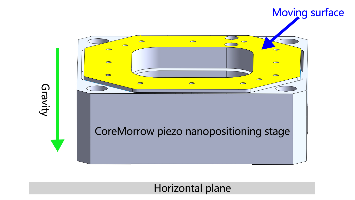
| Mounting Method |
Horizontal Mounting |
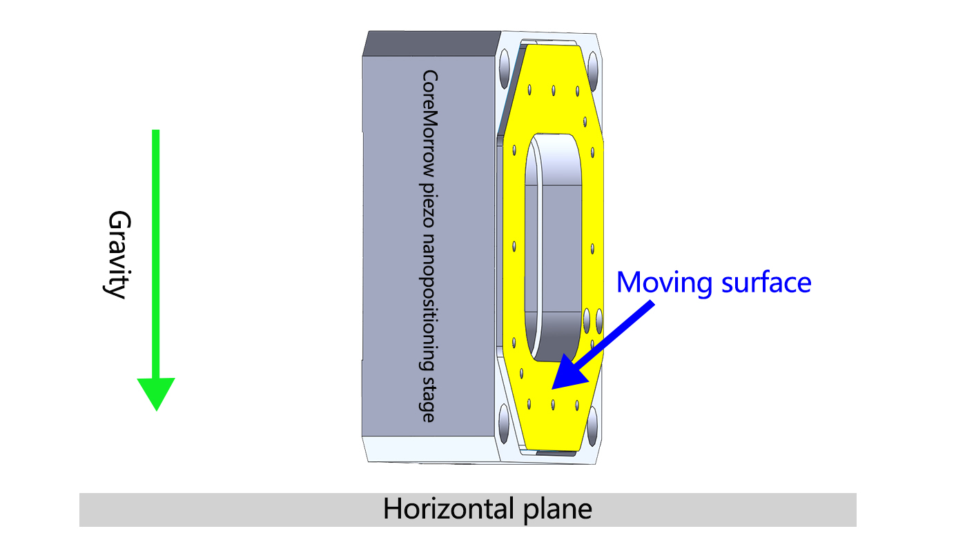
Vertical Mounting |
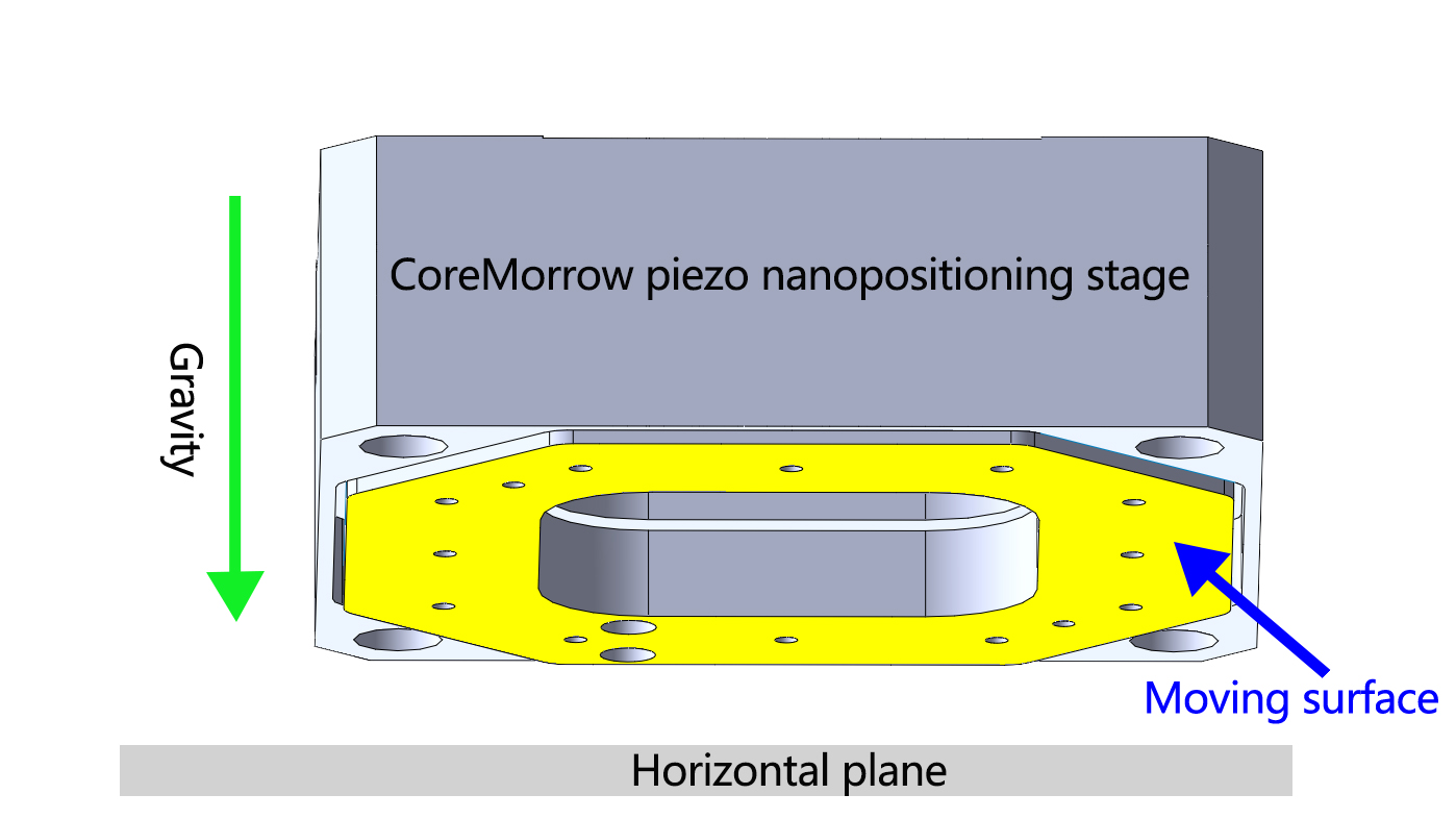
Inverted Mounting |
| Definition |
Place the PZT platform horizontally for installation, with the moving surface located above the PZT platform and parallel to the horizontal plane.
PS: Default direction for carrying capacity in the parameter table
|
Place and install the PZT platform vertically, with the moving surface parallel to the direction of gravity
|
Place the PZT platform horizontally, but the moving surface is located below the PZT platform |
| Diagram |
 |
 |
 |
| Note |
When the mounting method is selected as vertical mounting, pay attention to the outlet port |
||
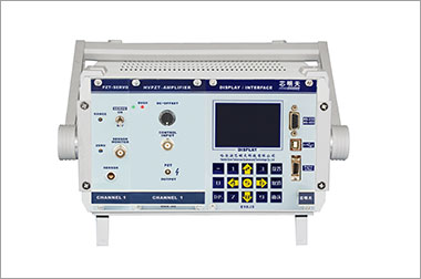
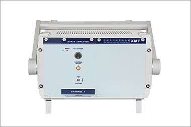
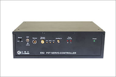
Recommended Controller
|
|
|
|


Sweep, get the latest information on core tomorrow
Address:1F, Building I2, No.191 Xuefu Road, Nangang District, Harbin, China
Tel:0451-86268790
Piezo · Nano · Motion
