

- Introduction
- Feedback
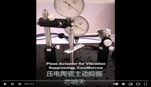
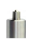
Low voltage preloaded piezo actuator is obtained by encapsulating the low-voltage piezo stacks inside, the outer part is protected by stainless steel casing, and the pre-tightening force is applied to the piezo stacks through the mechanical casing, the higher internal machinery preload force is suitable for high load, high dynamic applications. It could output the displacement and output generated by the piezo stack and could withstand certain tensile force.
Characteristics

|
|
|
|
|

|
Structure 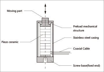
|
Higher Height Larger Displacement 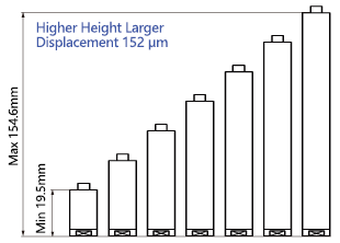
|
Closed Loop Curve 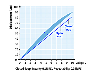
|
Applications
|
|
|
|
|
| Technicale data | |||||||||||||
|
Models |
Stroke |
Stiffness |
Push/pull force |
EI.capacitance |
Resonant frequency |
Weight |
Length L |
Downloads |
Step |
||||
|
Internal thread |
Plane |
Spherical |
Extermal thread |
||||||||||
|
PSt150/7/7 VS12 |
9 |
120 |
1200/200 |
0.7 |
40 |
34.6 |
19.5 |
|
|
|
|
||
|
PSt150/7/20 VS12 |
19 |
60 |
1200/200 |
1.8 |
30 |
18.7(with black and red wires) |
28.5 |
|
|
|
|
||
|
PSt150/7/40 VS12 |
38 |
25 |
1200/200 |
3.6 |
20 |
- |
46.5 |
|
|
|
|
||
|
PSt150/7/60 VS12 |
57 |
15 |
1200/200 |
5.4 |
15 |
- |
64.5 |
|
|
|
|
||
|
PSt150/7/80 VS12 |
76 |
12 |
1200/200 |
7.2 |
12 |
46.8 |
82.5 |
|
|
|
|
||
|
PSt150/7/100 VS12 |
95 |
10 |
1200/200 |
9 |
10 |
- |
100.6 |
|
|
|
|
||
|
PSt150/7/120 VS12 |
114 |
8 |
1200/200 |
11 |
8 |
241.2 |
118.6 |
|
|
|
|
||
|
PSt150/7/140 VS12 |
133 |
7 |
1200/200 |
13 |
6 |
- |
136.6 |
|
|
|
|
||
|
PSt150/7/160 VS12 |
152 |
6 |
1200/200 |
15 |
5 |
99.9 |
154.6 |
|
|
|
|
||
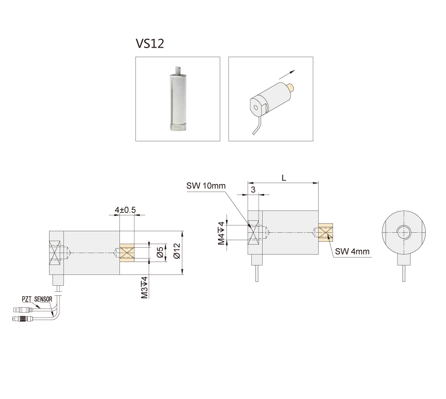
*Nominal Stroke corresponding drive voltage 0-150V, Recommended voltage 0~120V for long-term operation to extend lifetime.
|
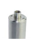
Standard end |
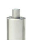
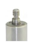
Optional ends |
|||||
|
Internal |
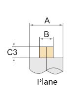
Plane |
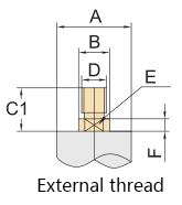
External |
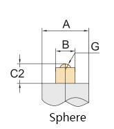
Sphere |
|||
|
|
|
|
|
|||
|
See above drawing |
|
|
|
|||
|
See above drawing |
Symbol |
Parameter |
Symbol |
Parameter |
Symbol |
Parameter |
|
A: |
Ø12 |
A: |
Ø12 |
A: |
Ø12 |
|
|
B: |
Ø5 |
B: |
Ø5 |
B: |
Ø5 |
|
|
C3: |
4±0.5 |
C1: |
7±0.5 |
C2: |
5±0.5 |
|
|
|
|
D: |
M4 |
G: |
SR1.5 |
|
|
|
|
E: |
SW4mm |
|
|
|
|
|
|
F: |
2 |
|
|
|

Sweep, get the latest information on core tomorrow
Address:1F, Building I2, No.191 Xuefu Road, Nangang District, Harbin, China
Tel:0451-86268790
Piezo · Nano · Motion
