
E00.A14 Piezo Controller, Driving 12 Pieces Three-wire Piezo Bender at Once!
CoreMorrow piezo driver is a kind of piezo ceramic driver with variable output voltage and variable frequency. The output voltage signal can be used to drive the isocapacitive load of piezo ceramics.
E00.A14 piezo controller is one of CoreMorrow E00/E01 series products, this series of products have the characteristics of modular and free combination, so the customers can choose the modules according to their demand.

E00.A14 piezo controller which contain 12 variable voltage channels and 2 constant voltage output channels, is assembled to simultaneously drive 12 piezo benders.
For better understanding of the use of E00.A14 piezo actuators, we start with the piezo bender, usually the piezo benders driven by three wires is more common. Take the CoreMorrow piezo bender as an example, it has red, blue and black driving leads.
Three-wire Piezo Bender

The structure of the relatively simple bender is composed of piezo ceramic sheet in the top, metal substrate in the middle, and piezo ceramic sheet at the bottom, and the upward and downward bending motion is generated through the coordination of the micro-displacement changes of the two ceramic sheets. The structure is shown on the left below figure.
In addition, CoreMorrow also provides multi-layer piezo benders, the interior is composed of a lot of piezo layers and electrode layers. The thickness of each layer is about tens of microns. The internal structure is shown below on the right.
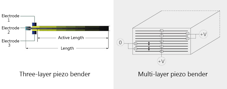
The driving mode is similar whether the structure is three-layer or multi-layer. The three leads are connected respectively with positive constant voltage, negative constant voltage and variable voltage for control.
CoreMorrow Piezo Bender Parameters
|
|
[mm] |
[μm] |
[N] |
|
|
|
|
|
|
|
|
|
|
|
|
|
|
|
|
|
|
|
|
|
|
|
|
|
|
|
|
|
|
|
|
|
|
|
|
|
|
|
|
|
|
|
|
|
|
|
|
|
|
|
|
|
|
|
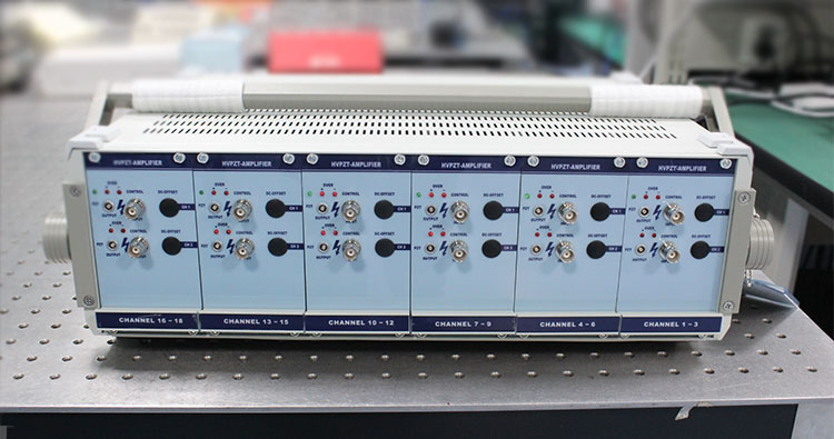
E00.A14 Piezo Driver
The E00.A14 piezo controller uses an E03 power amplifier module, each module has three output channels, and each channel outputs a variable voltage of +100V to -100V. Its panel interface is defined as follows.

The piezo controller is controlled by the analog input, that is, the analog signal provided by the external source, such as the signal generator. After the external analog signal is amplified by E00.A14 piezo controller, the output meets the high voltage of the piezo bender.
E00.A14 Basic Technical Data
|
|
|
|
|
|
|
|
|
|
|
|
|
|
|
|
|
|
|
|
|
Connection of E00.A14 piezo controller and piezo bender
Taking CoreMorrow multi layer piezo bender NAC series as example, we can see the connection between 12 benders and E00.A14 piezo controller. The connection lead of piezo bender is defined as shown in the figure below.

For the connection of 12 piezo benders to E00.A14, the red lines of each piezo bender are connected together, and then connected to the constant voltage +100V output connector of the E00.A14 piezo controller, the two can be connected by LEMO wire to fish clip wire, or by prefabricated leads with connectors. Similarly, the black wires of each piezo bender are connected together, and then connected to the constant voltage -100V output connector of E00.A14. The blue wire of each piezo bender is the control voltage lead, which needs to be separately connected to a connector of the variable voltage output channel on the E00.A14. As shown in the picture below.

Through the above connection, the E00.A14 piezo controller can simultaneously control the motion direction, displacement and motion frequency of 12 piezo benders.
In addition to the E00.A14 piezo controller, we have hundreds of other models, which can output any voltage range within 2000V range. For any piezo ceramic controller selection, you are welcome to contact phone no. 0451-86268790, 17051647888 (wechat ID)!
 12 channels, -300 ~ +300V voltage output
Sweep, get the latest information on core tomorrow
Address:1F, Building I2, No.191 Xuefu Road, Nangang District, Harbin, China
Tel:0451-86268790
Piezo · Nano · Motion
