

3D Fiber End Detection Based on Piezo Stage/Phase Shifter Adjustment
The optical fiber connector is a detachable (movable) connection device between the optical fibers. It precisely connects the two end of the optical fiber so that the light energy output by the transmitting optical fiber can be coupled to the receiving optical fiber to the maximum extent. At the same time, it minimizes the impact on the system due to its involvement in the optical path. Optical fiber connector is the most widely used product in optical communication passive components, and its quality directly affects the transmission efficiency and performance of optical fiber communication. In order to achieve the best state of insertion, return loss and interchangeability, there are many testing equipment on the market to ensure the quality of optical fiber connectors.
The traditional end face detector can quickly detect whether there are contaminants, scratches, defects and other unqualified factors on the end face. However, for the end face of the optical fiber connector to be used in some occasions, it is impossible to determine whether it is qualified only by the judgment of these factors. Therefore, the technology that can detect the 3D parameters of the fiber end face came into being.
///////////////
3D Inspection System & Its Principle
At present, the commonly used method for the detection of three-dimensional parameters of optical fiber end faces is optical interference. Optical interference is based on the fact that when coherent light meets in space, it always increases in some areas and always weakens in some areas, forming a stable distribution of strength and weakness. The 3D interferometer system used in the actual measurement is designed according to this principle, and its structure is shown in Figure 1.

Figure 1. Optical fiber connector end face detection interference system
The main working principle of the 3D interferometer system is that the light emitted by the light source is reflected by the semi-lens to the interference objective lens, and the light is focused on the end face of the light connector to be detected, and after being reflected by the end face, it passes through the semi-lens together with the reflected light from the reflective surface of the interference objective lens to form an image in the CCD camera. At this time, interference fringes can be observed on the CCD camera. The image measured by the CCD camera is transmitted to the computer via the image card for analysis and processing. You can get the required measurement results. The PZT piezoelectric nano positioning stage/phase shifter controlled by the computer through the control card and the control loop is used to move the interference objective lens to produce phase shift.
For the measurement of the shape of the fiber end face, the generally adopted method is the phase shift method with higher analytical accuracy. The principle of the phase shift method is to control the PZT piezoelectric nano positioning stage/phase shifter to move the interference objective lens and produce phase shift. After each movement, the CCD camera reads the interference fringes, and calculates the end face shape according to the interference fringe distribution.
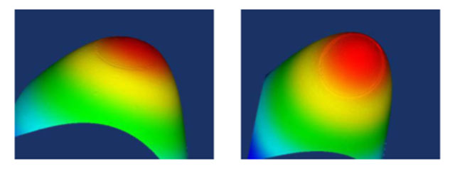
Figure 2. 3D morphology of fiber end face
It can be understood from the above principles that the step accuracy of the PZT piezoelectric nanopositioning stage/phase shifter determines the detection accuracy of the 3D interferometer system.
The PZT piezoelectric nano-positioning stage, piezoelectric actuator, and piezoelectric phase shifter products manufactured by CoreMorrow have been widely used in interference systems. In the phase shift adjustment process, it can provide nano-level stepping resolution and precision,making the test performance of the interferometer system more stable and accurate.
///////////////
Coremorrow Piezo Nano Positioning Stage/Phase Shifter
Piezoelectric Ceramic Actuator—Small Volume Phase Shifter
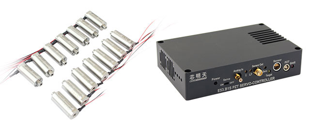 CoreMorrow's piezoelectric ceramic actuator has the characteristics of small size, nanometer-level high precision, and millisecond-level response speed. Its outer diameter can be as small as 9mm. It is more suitable for interference systems in confined spaces when matched with CoreMorrow E53 series of small-volume piezoelectric controllers.
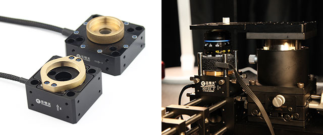
The P70 series piezoelectric nano positioning table is specially designed for cage structure with cage structure mounting holes reserved at the four corners. The standard product has XY motion version (stroke 17μm), Z motion version (stroke 8μm), and XYZ motion versions are also avaliable.
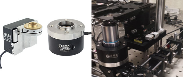
CoreMorrow has a variety of piezoelectric objective lens positioners dedicated to the nano-level step adjustment of the objective lens. It can be integrated into the cage structure or any interference system. The shape is compact, and the stroke is optional from 50μm to 1mm, up to the resolution of 2.5nm can meet the step accuracy requirements of the interference system.
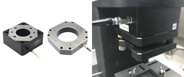
There are hundreds of types of CoreMorrow piezoelectric phase shifters. For large-aperture laser interferometers, CoreMorrow specially designed P77 series piezoelectric phase shifters. The aperture is optional from φ36mm to φ310mm, and can be customized according to need. It can complete the rapid adjustment of 0.5nm step in the millisecond range.
///////////////
- Previous article:H01.9 Series Piezoelectric Optical Fiber Phase Shifter
- Next article:N31 Series Linear Piezoelectric Motor
Sweep, get the latest information on core tomorrow
Address:1F, Building I2, No.191 Xuefu Road, Nangang District, Harbin, China
Tel:0451-86268790
Piezo · Nano · Motion
